Step-by-Step Instructions
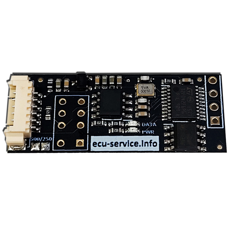
1. Connecting the Device:
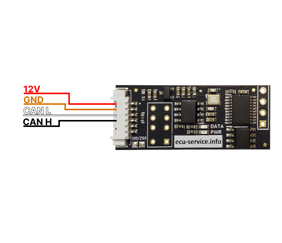
- Connect the CAN-SENDER to the power supply in the vehicle or on the test bench.
- Ensure that all wires are properly connected to the CAN bus.
2. Selecting CAN Speed:
- Go to address 0x00 to set the CAN speed.
Enter :
- 0x00 for 125 kbps.
- 0x01 for 250 kbps.
- 0x02 for 500 kbps.
- 0x03 for 800 kbps.
3. Configuring CAN Frames:
- You can input CAN frames starting from address 0x10 to 0x1F0.
- Up to 31 frames can be sent simultaneously.
- The frame has the following structure:
00 00 00 11 08 11 22 33 44 55 66 77 88 FF FF 01
- Frame ID
- 0 – standard frame, 1 – extended frame.
- Data length (0-8 bytes).
- Data: Enter the corresponding data values.
- Time interval (e.g., how often the frame should be sent).
- Cycle count: How many times the frame should be sent.
4. Monitoring LEDs:
- Red LED blinks, green LED off: CAN speed error or improperly soldered EEPROM memory.
- Red LED on, green LED off: No data entry to send.
- Red LED on, green LED blinks every 800ms: Data is being sent correctly.
----------------------------------------------------------------------------------
Examples of Configuration:
1. Sending a single standard frame immediately after power on
Configuration:
00 00 00 11 08 11 22 33 44 55 66 77 88 FF FF 01
Description:
- Frame ID: 0x11 (Standard ID)
- Frame type: Standard (0x08)
- Data length: 8 bytes (0x08)
- Data: 11 22 33 44 55 66 77 88 (8 bytes of data)
- Interval: FF FF (Single send immediately after power on)
- Cycle count: 1
2. Sending a single extended frame immediately after power on
Configuration:
00 00 00 11 18 11 22 33 44 55 66 77 88 FF FF 01
Description:
- Frame ID: 0x11 (Extended ID)
- Frame type: Extended (0x18)
- Data length: 8 bytes (0x08)
- Data: 11 22 33 44 55 66 77 88 (8 bytes of data)
- Interval: FF FF (Single send immediately after power on)
- Cycle count: 1
3. Sending a single standard frame 4 seconds after power on
Configuration:
00 00 00 11 08 11 22 33 44 55 66 77 88 40 00 01
Description:
- Frame ID: 0x11 (Standard ID)
- Frame type: Standard (0x08)
- Data length: 8 bytes (0x08)
- Data: 11 22 33 44 55 66 77 88 (8 bytes of data)
- Interval: 40 00 (4-second delay)
- Cycle count: 1
4. Sending a standard frame 10 times every 100ms
Configuration:
00 00 00 11 08 11 22 33 44 55 66 77 88 01 00 10
Description:
- Frame ID: 0x11 (Standard ID)
- Frame type: Standard (0x08)
- Data length: 8 bytes (0x08)
- Data: 11 22 33 44 55 66 77 88 (8 bytes of data)
- Interval: 01 00 (100ms interval between cycles)
- Cycle count: 10
5. Sending a frame with 5 bytes of data
Configuration:
00 00 00 11 05 11 22 33 44 55 FF FF FF FF FF 01
Description:
- Frame ID: 0x11 (Standard ID)
- Frame type: Standard (0x05 – 5 bytes of data)
- Data: 11 22 33 44 55 (5 bytes of data)
- Interval: FF FF (Single send immediately after power on)
- Cycle count: 1
6. Sending a frame with 8 bytes of data with a 100ms interval (loop)
Configuration:
00 00 00 11 08 11 22 33 44 55 66 77 88 01 00 FF
Description:
- Frame ID: 0x11 (Standard ID)
- Frame type: Standard (0x08)
- Data length: 8 bytes (0x08)
- Data: 11 22 33 44 55 66 77 88 (8 bytes of data)
- Interval: 01 00 (100ms interval)
- Cycle count: FF (loop every 100ms)
----------------------------------------------------------------------------------------------
Automotive Applications:
CAN-SENDER can be used in diagnostics, testing of communication systems in vehicles, monitoring CAN buses, simulating and sending messages to various electronic systems in vehicles, such as ECU (Electronic Control Unit), ABS systems, engine controllers, etc.
Practical Applications in the Automotive Industry:
1. Vehicle Diagnostics
- Use: CAN-SENDER can be used to simulate and test communication on the CAN bus in automotive repair shops and diagnostic centers. It allows monitoring the performance of various modules in vehicles.
- Example: A mechanic receives a car with a CAN bus communication error. Using CAN-SENDER, they can quickly check if the problem is related to a specific module (e.g., ABS controller) by simulating CAN messages sent to that module and observing the response. They can also monitor and analyze the replies to identify cable or module failures.
2. ECU Programming and Configuration
- Use: CAN-SENDER allows sending CAN frames to the ECU for updating settings, testing signals, or performing ECU programming.
- Example: In a tuning workshop, an engineer needs to change the ECU settings responsible for turbocharger control. With CAN-SENDER, they can send modified CAN frames without the need to disassemble the system. The tool enables quick updates and testing of new settings.
3. Retrofit and Vehicle Tuning
- Use: CAN-SENDER can be used by companies specializing in vehicle tuning that need access to the CAN bus to modify vehicle parameters, such as safety systems or engine control settings.
- Example: A company that specializes in modifying cars installs a new ambient lighting system controlled via CAN. CAN-SENDER allows them to send and test CAN messages to ensure that the lighting system functions as intended, reacting to events like door opening or vehicle startup.
4. Technical Training
- Use: The product can be used in technical schools and universities to teach students about CAN bus principles and allow practical testing of various communication scenarios.
- Example: During technical training for automotive students, the instructor uses CAN-SENDER to demonstrate how the CAN bus works in practice. Students can simulate various failure scenarios and learn how to diagnose communication issues between control modules in vehicles.
The product is made and developed by ECU SERVICE.